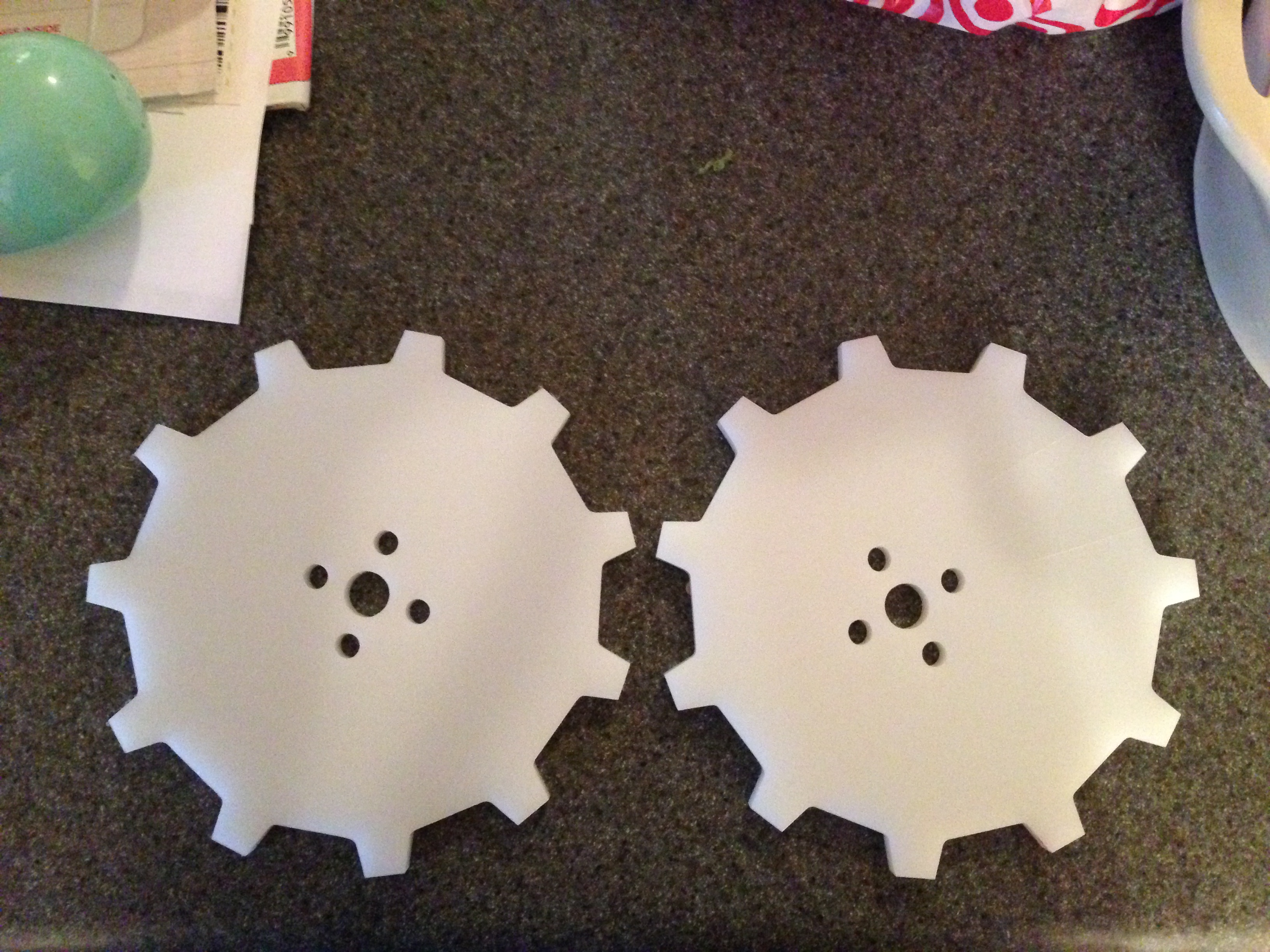
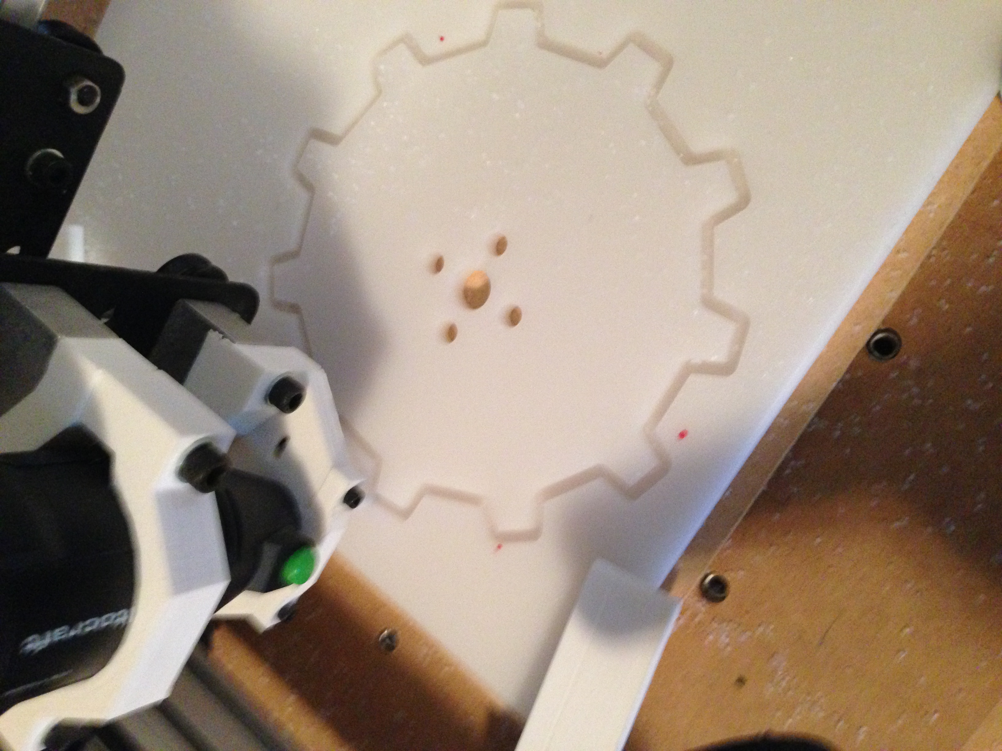
My first collaborative Shapeoko milling job was cutting gears out of 8mm HDPE, more commonly known as cutting board. Running someone else’s gcode was a new experience. My workflow to date with the Shapeoko has been vector files in Inkscape and generating gcode in makercam.com. I did several iterations back and forth with Nathan generating gcode and me visualizing it in Universal GCode Sender, UGS. The learning curve involved figuring out what information Nathan needed to create code that worked on my side. This article describes what we learned.
Material Parameters
Establish a baseline for the machine and material. Keep notes.
The admins at the Shapeoko forum have done a great job in capturing material parameters as users post messages. The Materials page of their wiki has several materials with suggestions for cut depth, speed, endmill selection, and other parameters. Pay attention to endmill selection and the spindle used. I wouldn’t expect similar results using a Dremel knockoff compared to a Dewalt DW660. I stayed conservative with new material. It helps that HDPE is inexpensive and forgiving. Keep notes on what values you use. I always wish I had written something down. I can’t recall the last time I regretted keeping notes.
Endmill Parameters
Know the bit size, type, cutting length.
The stock spindle for the Shapeoko 2 is a generic Dremel knockoff with 1/8″ collet. I picked up a set of starter bits that included a 2 flute straight 1/8″ endmill. There are lots of options here. I chose the endmill based on the material page suggestions and the bits I had on hand.
Controller Software
Generate gcode for the specific controller. Use a generic profile for grbl if it’s not specifically available.
The 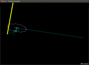 stock Shapeoko 2 controller runs grbl. Each CNC controller supports a subset of gcode commands. The CAM software used to generate the gcode needs to know what commands your mill accepts. The first couple iterations had me loading the gcode in UGS, visualizing it, and doing an air mill to understand what I was seeing. The visualizer gave me an idea of the mill movements. UGS knows what gcode commands grbl accepts. Quickly looking at the visualizer things were obviously not what we expected. The console in UGS also had lots of complaints about skipped commands.
I believe the visualizer is telling me the mill is going to make a few cuts in the center of the gear and then head off in the +X direction. Doing an air mill this is pretty much what happened.
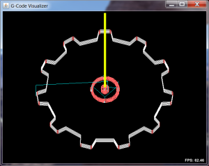 Once we understood the issue Nathan generated code that was usable by the grbl controller for the Shapeoko. He was also able to sanity check by running the visualizer in UGS without needing access to the mill. This screen shot makes more sense. You can see the pocket cuts in the center of the gear along with each step down in depth. Compare to the first try notice there are no iterations. The first attempt looks like drilling. Also notice the profile around the gear. The steps down are clearly visible in the second attempt.
Note the yellow vertical line marking the spindle position at the start of the gcode. It’s right in the center of the gear. I compensated for this by trying to center the starting 0,0,0 position of the spindle in an appropriate spot on the work piece. During the first run I realized there wasn’t enough room in the -X direction and crashed the gantry. The result was an off-center gear.
Working Limits
You will crash. Know the millable area, safety heights, and cut depths.
My experience with crashing the Shapeoko mill has been painless so far. Crashing refers to instructing the mill to move to a place beyond it’s working limits. The results can vary from “oh shit” to “oops” depending on what you hit. Crashing brings up the need for limit switches and an emergency switch. I have an e-switch, but no limit switches.
Conclusion
I think my first collaborative Shapeoko job went well. I learned a lot about what I need to communicate with someone creating gcode. Generating gcode is not universal compared to printing a document. It’s very much just a start. During my iterations with Nathan some things we didn’t address were safety heights, end depths for the material, and using tabs. The safety height sets the spindle height when moving the mill to the next work position. This job started at 0,0,0 and moved in +X direction at 0 Z over to the first hole. This left a nice unintended shallow cut. The end depth compensates for cutting all the way through the material. You don’t want to waste time cutting too deep in to the waste board below the material, but you also want a through cut. Adding a -.1 to -.2mm to the depth is enough assuming things are relatively plane. We also managed to get by without having tabs or something holding the finished piece in place. Tabs are adding by CAM to keep the piece in place preventing it from freely jumping out and causing chaos.
I’d appreciate comments on what other things a gcode creator and milling operator need to know to collaborate.